Connectors & cables
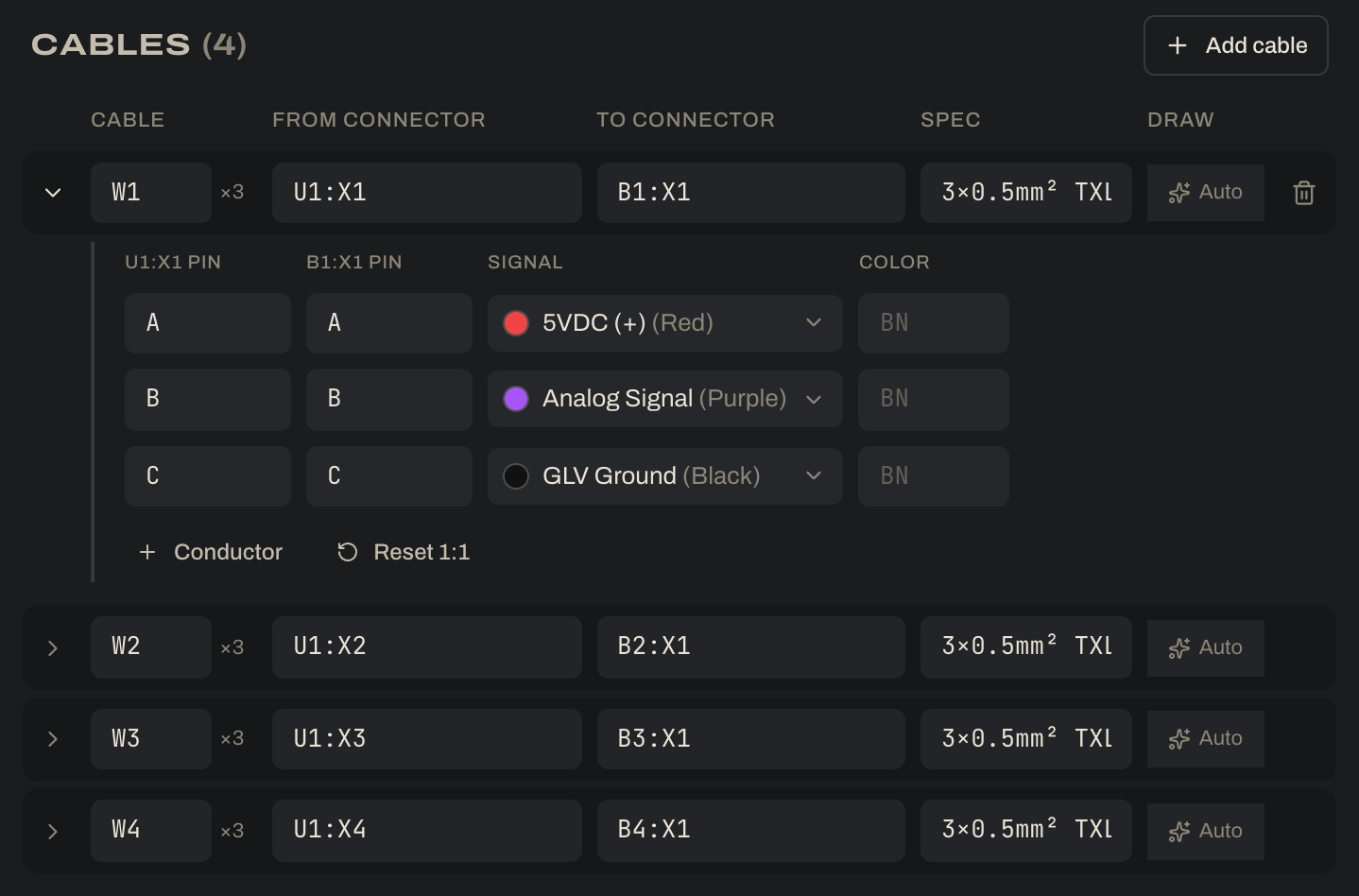

A cable (W1, W2…) joins two connectors pin for pin. In the example, W1 runs from the VCU’s sensor port U1:X1 to the first accelerator pedal sensor B1:X1: 5V reference on A, signal on B, sensor ground on C. Cables are listed above the wiring schedule, and each one stands for all of its conductors.
- Add cable, then pick both ends as
TAG:CONNECTOR. Pins map 1:1: by name when both sides use the same pin names (A→A, B→B, C→C, as here), otherwise in pin order. - Open a cable’s pin map to change which pins connect, cross pins over, add or remove conductors, and set each conductor’s signal and color (IEC codes: BN, WH, BU, BK, GN/YE…).
- Changing an end resets the pin map to 1:1 and keeps the conductor colors. Reset 1:1 does the same on demand.
- The Spec text is printed on the bundle. The example uses it for wire and purpose:
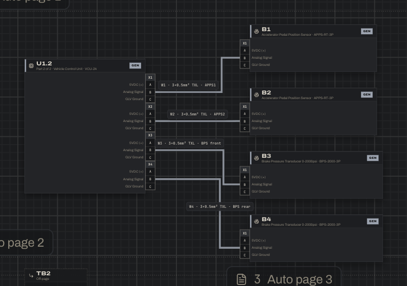
3×0.5mm² TXL · APPS1. - Mating check: a cable is flagged when both ends have the same gender, the keying differs, the pin counts differ, or a conductor points at a pin that no longer exists. That’s why the VCU has one 3-pin port per sensor rather than one large connector: every cable mates cleanly.
On the drawing a connector is a pin column flush against its block’s side (a band along the top or bottom in top-to-bottom flow). Inside the block each pin shows the signal it carries. A cable is drawn as one heavy bundle labelled with its tag and spec. The PDF wire schedule still lists every conductor individually.