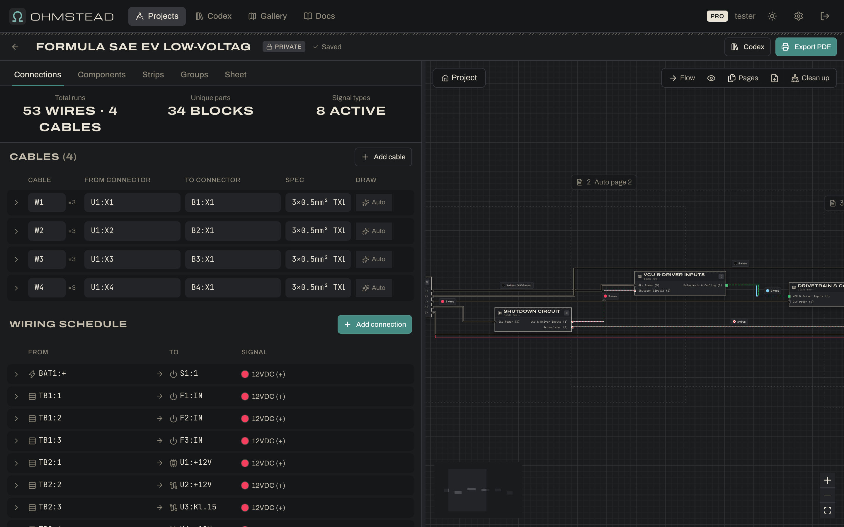
The example project
Every screenshot in these docs comes from the built-in Formula SAE EV Low-Voltage System template. It is the grounded low-voltage (GLV) side of an electric race car: everything that runs from the 12V battery rather than the tractive-system accumulator. Fork it from the Gallery to follow along.
- GLV Power: the 12V LiFePO4 battery
BAT1, the GLV master switchS1, and three fused branches:F1electronics,F2shutdown circuit,F3cooling. - Shutdown Circuit: the series loop that has to be closed before the accumulator can connect. It runs through the cockpit and side shutdown buttons
S2–S4, the brake over-travel switchS5, the inertia switchS6, the BSPDU4, the IMD and BMS fault contacts, the HVD interlockS7and the TSMSS8, and ends at the AIR coils. - VCU & Driver Inputs: the vehicle control unit
U1(split into two blocks), two accelerator pedal sensors and two brake pressure transducers on their own cables, the ready-to-drive button, the brake light and the ready-to-drive sound. - Accumulator: the BMS
U2, the insulation monitorU3and the two accumulator isolation relay coilsK1/K2. - Drivetrain & Cooling: the inverter’s low-voltage interface
U5, the coolant pump and the radiator fan, switched by VCU low-side outputs. - The driver display
U6sits at the top level, on the same CAN bus as the VCU, inverter and BMS.
The five subsystems are collapsed, so the top level reads as a compact system overview. Double-click any of them to work inside it. The project has 29 components, 54 loose wires, 4 sensor cables and 5 terminal strips, and passes validation with no warnings.