The wiring schedule
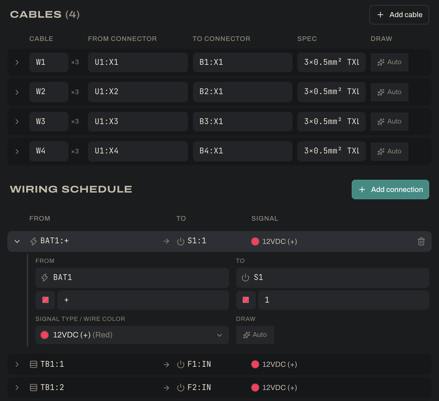

Each row in the Wiring schedule is one wire, shown as FROM_TAG:TERMINAL → TO_TAG:TERMINAL with its signal type. A wire is a fact about your system, not a line on a page: the same row drives the schematic, the PDF and the printed wire schedule. In the example, the row S8:2 → K1:A1 is the shutdown circuit reaching the AIR+ coil.
- Click the chevron at the start of a row to open its editor: both ends (tag and terminal), the connection type at each end, the signal type, a free-text note and the draw mode. New or unfinished rows open by themselves, and they stay visible even when you’re working inside a subsystem.
- Click the arrow between From and To (it turns into ⇄ on hover) to reverse a wire. Direction matters for terminal strips: a wire that ends on a strip lands on its input side, and a wire that starts on a strip leaves from its output side.
- Type a tag that isn’t in the project yet and the Codex opens asking which part it is: pick an existing part, or create a new one.
- Type a terminal the part doesn’t have and you can add it in the Codex. If someone else made that part, Ohmstead first copies it into your own Codex (a fork) and points this project at your copy, so their original is left alone.
- Connector pins are written
X5.3(connector X5, pin 3). A single loose wire can land on one pin: the example’s VCU rear-harness outputs,U1:X5.1toU1:X5.8, are wired this way. - The glyph beside a terminal is its connection type (screw, spring, push-in, crimp pin…). Each wire starts with the type set on the part in the Codex. To use a different one for just this wire, open the row and change Connection type; the part itself doesn’t change.
- Picking a terminal that has a default signal type fills in the row’s signal type, so most rows only need their two ends.
- Deleting wires never deletes components. When a deletion leaves components with nothing wired, a notice offers to remove them (with Undo). Ignore it and they stay on the drawing as unwired blocks.